FAQ
SteinAir Products
Tubing
Our pitot static tubing is Nylon. This is flexible and durable and will last decades. It is rated for both extreme heat and cold conditions.
Fittings
Our pitot static fittings are durable and long lasting. Inside the holes of the fittings are a ring of teeth which grip the tubing for a secure fit. These have been proven to be very effective and do not leak.
They have teeth You must get a flush cut when cutting the tubing or it can be prone to leaking. We recommend using a P-510 Cutting tool to get a straight cut.
Leaks
Most often the tubing is leaking at a connection point. The two biggest reasons there is leaking is because it is leaking around the threads of a fitting or the tubing was cut at an angle.
These fittings come with sealant applied to the threads however, Teflon tape around the threaded fittings, same as you would with the plumbing in your home, may provide superior connection. You must also be sure to get a straight cut when cutting the tubing or it can be prone to leaking. Do not cut at an angle. We recommend using a P-510 Cutting tool.
Equipment Selection
- Select the avionics, systems, and accessories that best fit your mission, budget, and goals.
Panel Design
- We’ll work with you to design your panel layout.
- PDF revisions will be provided throughout the design process until a final layout is approved.
Metal Fabrication, Paint & Engraving
- Your panel is CNC machined and all required metal fabrication is completed, including rails, nutplates, rivets, and mounting hardware.
- The panel is professionally painted by our local automotive paint partner.
- Finally, the panel is laser engraved using the approved design.
Wiring
- We create wiring schematics for all avionics, switches, and circuit protection associated with the instrument panel.
- Custom wiring harnesses are built and all instrument interconnections are completed.
- Flying leads are provided for systems such as heated pitot, lighting, servos, magnetometers, and other aircraft connections.
- Every wire is labeled and color-coded to match the wiring documentation included with your panel.
Configuration & Bench Testing
- The completed system is powered up and thoroughly tested on our bench before shipment.
- We configure as much of the avionics system as possible. Final aircraft-specific settings and manufacturer-required configuration will be completed by the builder during installation.
- After successful testing, we photograph the completed panel and assemble all documentation before carefully packaging it for shipment.
Final Invoice & Shipping
- Once your panel is complete, we’ll prepare the final invoice for parts and labor.
- Your panel is securely packaged in a custom-built crate and shipped fully insured via UPS 3-Day.
- Track your shipment as it makes its way to your shop.
- Open the crate, install your new panel, and enjoy the results!
Builder Info


Transponder Antenna
- 104-12 Monopole Antenna
- This antenna can be mounted on bottom of fuselage -on the belly of the beast.
- 104-17 — ADS-B Monopole Antenna [ freq 978 MHz ]
- This antenna is for ADS-B only. This can also be mounted on the bottom of the fuselage.
- CI-105 — Blade transponder / ADS-B antenna.
- This can be mounted on top or bottom of the fuselage.
Radio/Com Antenna
- CI-121 / CI-122
- This antenna should be mounted on the bottom of the aircraft, typically under the pilot. If two com antennas are being installed, they should be 3 feet apart.
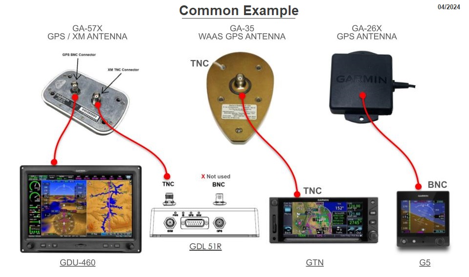
GPS Antennas
- GA-35 – WAAS GPS Antenna
- This antenna should be mounted on the top of the aircraft, either in front of or behind the canopy. It should not interfere with opening the canopy. If there are two GPS antennas being installed they can be mounted in-line or offset. Mount them at least 6 inches apart. Typically used with Garmin GTN units.
- GA-26X – Internal Mounted GPS Antenna (formally GA-26C)
- This antenna can be mounted on the glare shield or on a mounting plate behind the panel. Typically used for the PFD and/or MFD gps source.
- GA-57x – Combo XM/GPS Antenna
- Garmin GPS + a Garmin XM receiver. This antenna should be mounted above the aircraft along the fuselage. Mount at least 6 inches away from other antennas. Typically used with G3X system with xm weather.
Flap Position
If you want intermediate stops or flap position feedback on the EFIS, install a Ray Allen POS-12 position sensor.
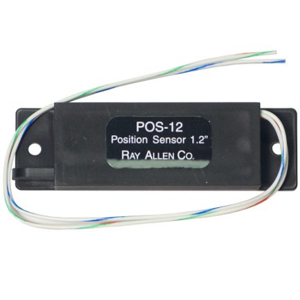
Where to mount the Ray Allen POS-12:
The POS-12 should be mounted so that a pushrod can be attached to both the POS-12 and to the bell crank on the flap system. The pushrod should be mounted a certain distance away from its center of rotation so that the position sensor arm moves 1 inch as the flaps move through their entire range of travel. This distance can be found through trial and error.
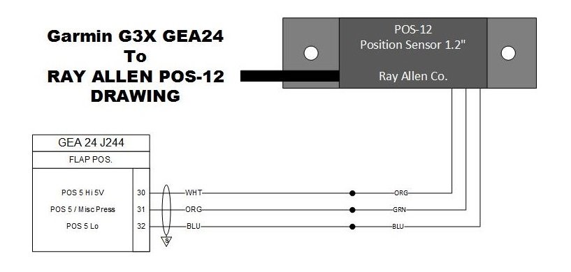
Wiring:
The flap position sense wires should either be wired to the G3X system via the GEA24 or wired to the Vertical Power system.
G3X Flaps
Flap Position:
Flaps/trim position can be wired to any available input on the GEA24 with “POS” in the name.
Flap Power:
G3X with Vertical Power:
Vertical Power: When using a Vertical Power unit, trim and flap positions will automatically be displayed. Connecting, configuring, and calibrating the POS inputs is not required when the position sensors are connected to a Vertical Power unit.
VPX Flaps
Vertical Power and G3X system:
When using a Vertical Power unit, trim and flap positions will automatically be displayed. Connecting, configuring, and calibrating the POS inputs is not required when the position sensors are connected to a Vertical Power unit.
G3X Trim Wiring
Refer to section 16 (GSA 28) of the latest G3X manual to learn more about trim.
16.5.2.3 Trim Motor Interface to a 3rd Party Motor
The GSA 28 provides an optional interface between the pilot’s electric trim switch and a 14 Vdc trim motor. This interface shall be used only when interfacing to a 3rd party trim motor. This interface is not to be used when a GSA 28 is being used as the trim actuator. When the GSA 28 servo is engaged (i.e. autopilot on) in the air, it automatically drives the connected trim motor as required to relieve control forces for the associated pitch, roll, or yaw axis.
When the GSA 28 servo is not engaged (i.e. autopilot off), it provides manual electric trim (MET) functionality by running the trim motor in response to pilot input. The GSA 28 can be configured to automatically reduce the speed of the trim motor at higher airspeeds, in order to provide finer control of trim tab position. In the event that power to the GSA 28 is removed, a fail-safe system connects the trim input switch directly to the trim motor. In this condition, the trim switch powers the trim motor directly and the motor runs at its full speed when the switch is pressed. The same condition also occurs if a trim switch and motor are connected to the GSA 28, but the trim control function is disabled.
G3X with GAD-27 Trim Wiring
The GAD 27 has 4 active low Roll and 4 active low Pitch discrete inputs that allow for manual control of pitch trim motors. Pilot
switches take priority over copilot switches when they disagree unless pilot switches are both inactive. Copilot trim switches are optional.
Refer to section 23 of the latest G3X Manual.
23.13.7 Trim (G3X Touch™ Avionics Installation Manual. Rev. AZ. Page 23-56)
The trim inputs should connect to the panel trim switch. The trim outputs should connect to the trim servo, maximum output current of the trim outputs is 1 Amp. If the GSA 28 is not powered, a fail-safe feature causes the trim inputs to connect directly to the trim outputs. If the servo is powered and configured for speed scheduling, the servo drives the trim outputs based on the trim inputs and aircraft speed. If the servo is powered with the autopilot and auto trim feature is enabled, the servo has full control of the trim outputs.
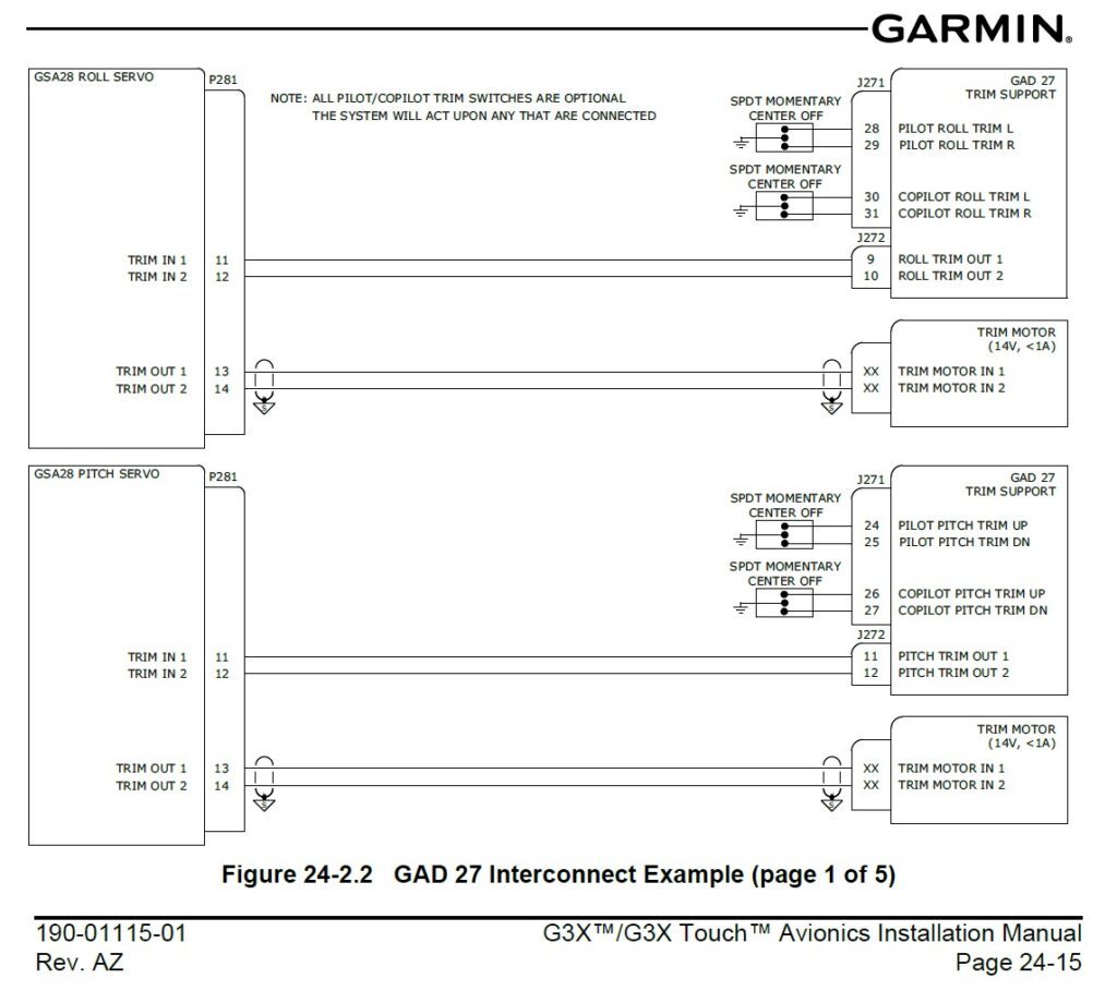
GAD 27 Trim planning, from G3X manual
VPX Trim Wiring
The VP-X can control the trim motor as well as provides the circuitry to report the trim position to the EFIS. It also handles runway or faulted trim conditions, and enables the EFIS to control the trim from the screen. All of the trim wiring is connected directly to the VP-X, and the trim position is reported to the EFIS over the serial data line. The trim motor circuit breakers are set at 1 amp, and are not configurable.
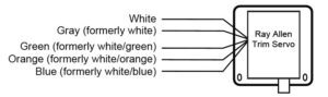
Most experimental aircraft use trim servos from the Ray Allen Company. These servos are self-contained units that include the trim motor as well as a position sensor. These servos are designed to run at 14 volts, and the VP-X Pro provides regulated 14v power to the trim motors so they can operate safely in 14v or 28v systems. The general principles described in this section apply to other brands of trim motor as well.
Connecting the trim motor to the VPX:
The trim motor itself is driven by a white and a gray wire (formerly two white wires). It does not matter how they are connected, as the polarity can be changed using the VP-X Configurator. The direction of travel is controlled by reversing the positive and negative connections to the trim motor. This is done conventionally using switches or relays, but is done in the VP-X with solid-state circuitry.
(See Section 5.19 Trim System Wiring. VP-X Install Manual, Rev G3, 2024 for more details)
Ray Allen Trim Position
Where to mount the POS-12:
The POS-12 should be mounted so that a pushrod can be attached to both the POS-12 and to the bell crank on the flap system. The pushrod should be mounted a certain distance away from its center of rotation so that the position sensor arm moves 1 inch as the flaps move through their entire range of travel. This distance can be found through trial and error.
Garmin Questions
To enter configuration mode:
- Press NRST, MENU and BACK simultaneously to reboot the GDU.
- Then continue to hold the MENU button while the screen is powering up.
This will enter config mode where you may change your settings.

To update your Garmin Aviation Databases go to https://fly.garmin.com/fly-garmin/ . The databases can be downloaded to a SD card and then loaded into your G3x System via the SD card slot on the display.
To update your Garmin Aviation Databases go to https://www8.garmin.com/support/collection.jsp?product=010-00G3X-00 . The databases can be downloaded to a SD card and then loaded into your Garmin Systems via the SD card slots on the displays.
We suggest reading the associated service bulletins for further instructions and information.
With multiple G3X screens, each individual screen will need new software updates loaded with an SD card. Software does not automatically get transferred over from screen to screen. It is important to have all screens on the same software version.
To calibrate the ADAHRS … see section 35.4.7 ADAHRS (Air Data Attitude/Heading Reference System) Calibration Page of the G3X Installation manual (rev AP).
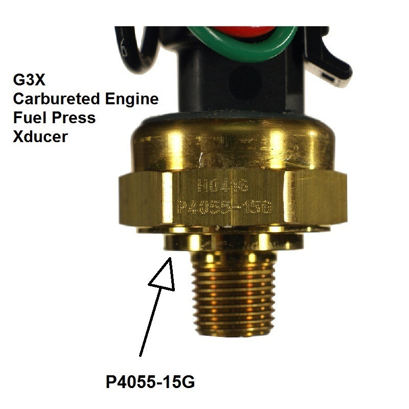
Carbureted Fuel Pressure Sensor, 15 PSI
On the G3X Carbureted fuel pressure transducer you want to look for the markings P4055-15G on the brass fitting.
Purchase link > G3X Fuel Pressure Sensor, Carbureted
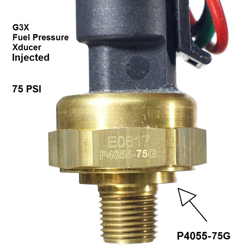
Injected Fuel Pressure Sensor, 75 PSI
There are currently two pressure transducers in circulation for the G3X Fuel pressure with Fuel Injected engines. Both sensors are 75 PSI sensors.
The original transducer, which was sold up until 2021 and has since been discontinued, was a black molded plastic housing with a brass fitting. (see below).
On the G3X Fuel pressure transducer you want to look for the markings P4055-75G on the brass fitting.
G3X fuel pressure sensor, injected 75 PSI (discontinued as of 2021)
The new fuel pressure transducer on the market is a chrome fitting. and looks like this:

Purchase link > Garmin G3X Fuel Pressure Sensor 011-05783-20
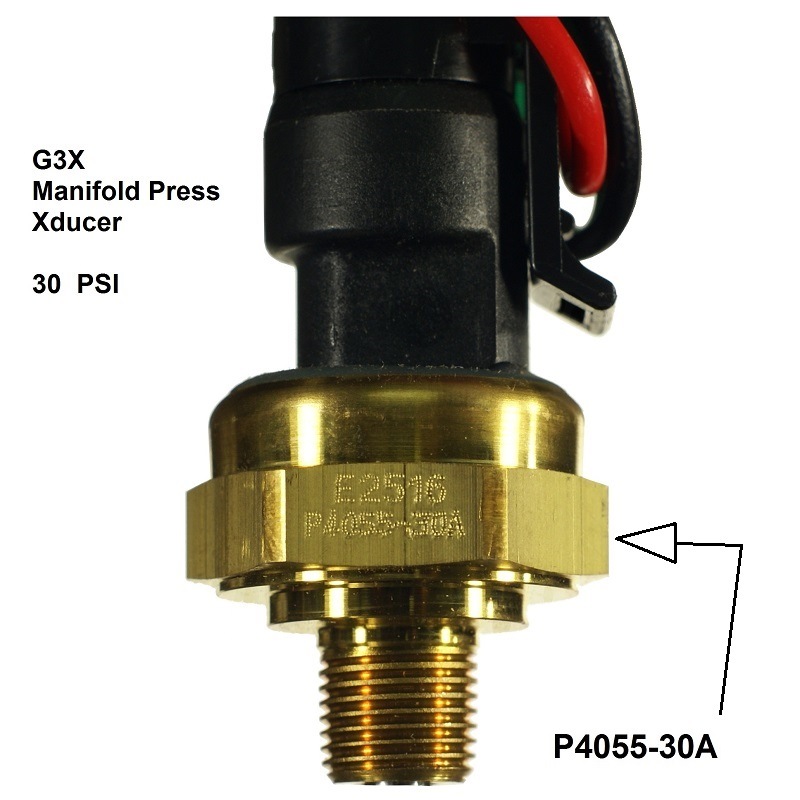
Manifold Pressure Transducer, 30 PSI
There are currently two pressure transducers in circulation for the G3X manifold pressure. Both sensors are 30 PSI sensors.
The original transducer, which was sold up until 2021 and has since been discontinued, was a black molded plastic housing with a brass fitting. (see below).
On the G3X Manifold pressure transducer you want to look for the markings P4055-30A on the brass fitting.
G3X Manifold pressure sensor > (discontinued as of 2021)The current G3X-Manifold sensor is a chrome fitting and looks like this:
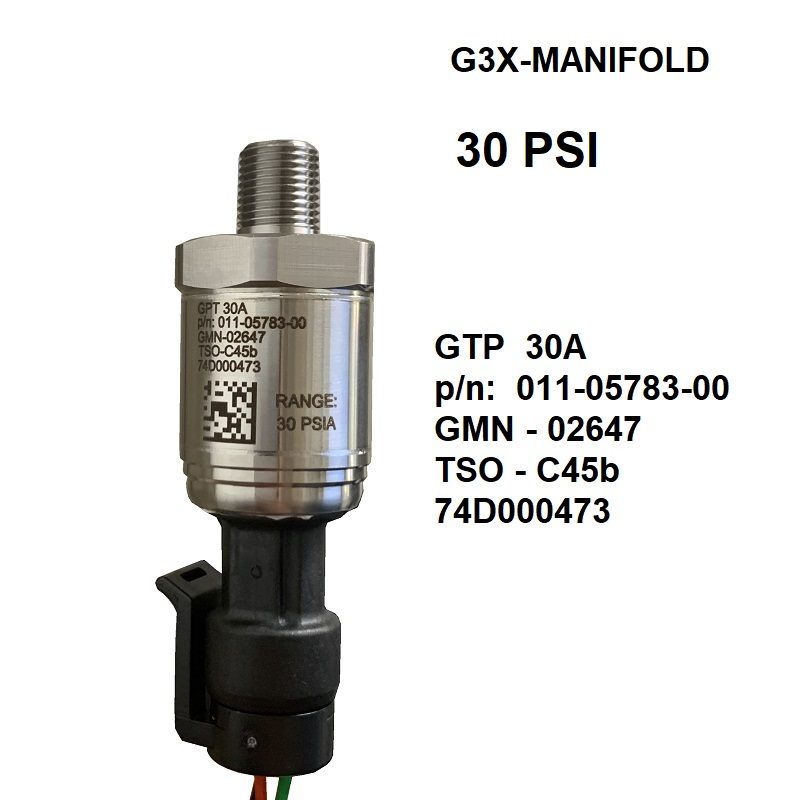
Purchase link > Garmin G3X Manifold Pressure sensor 30 PSI p/n: 011-05783-00
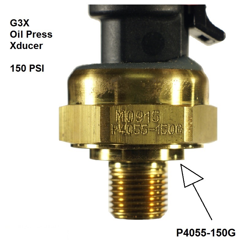
Oil Pressure Sensor, 150 PSI
On the G3X Manifold pressure transducer you want to look for the markings on the brass fitting.
The piece should have this marking on it: P4055-150G
G3X Oil pressure sensor 150 PSI 494-30004-00
G3X-OIL-PRESS Sensor
Dynon Products
How to enter Configuration Mode?
On the Dynon Skyview System. Press + Hold down the two soft keys on the right hand side of the screen for a few seconds. This will put the screen in configuration mode.